Turning Non-domestic space to Domestic usage for Public Rental Housing
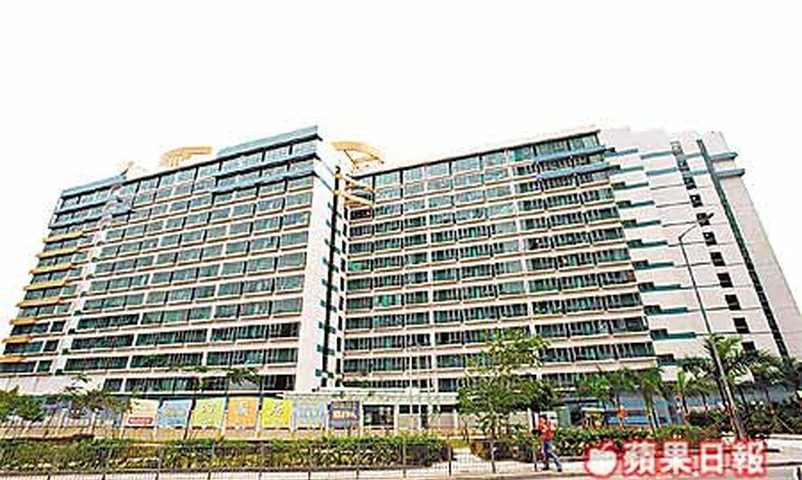
To boost the housing supply is the urgent needs in today HK. Although many resources such as transitional housing and new town development are allocated , GBE has been working on two interesting cases which are to convert the “non-domestic space” to domestic usage. We love to sharing our experience to all reader.

Technical Hurdle for conversion 

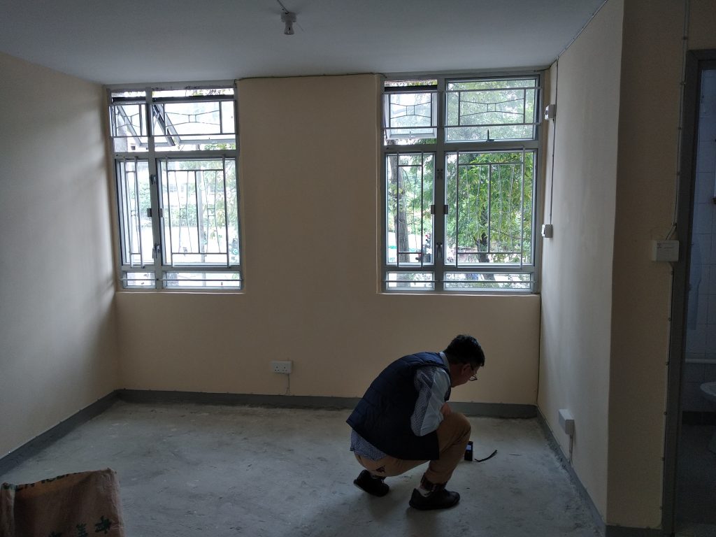
There are many technical consideration to the conversion. To list some, the issues cover the “GFA” , “site coverage”, natural lighting and ventilation, open space, Fire safety are all in the radar . On top of this , some tricky issues such as concrete cover ; width of re-entry for open space; barrier free access ; provision of gas aperture , Kitchen, sanitary fitment and the clear headroom for the domestic space are all counting on.

Overcome the hurdle

It is technically complex to resolve all the issues in one scheme. We have to prioritise the amount of effort to resolve each problem. Honestly , some of the technical hurdle may be too costly to resolve or even not possible to overcome

  • GFA and site coverage is the most tricky

Among all the hurdles, the GFA and site coverage are the most pertinent and profound factor. We have had a blog talking about the GFA conversion. Honestly , in the case of conversion, we usually have to rebuild the entire GFA calculation and site coverage from scarp. It boils down to the classification of site, open space and roof cover area. It is highly tedious but technical process.

  • Lighting and ventilation / fire safety 

Many peers usually have the impression that these are resolvable and always undermine the inherent difficulties. Let us share you one point, the importance of the RHS and prescribed windows are always in the play. Since the RHS is dictated much by site surrounding and site boundary, it eventually restricts the design of light/ventilation very much

The same hurdles happens to the fire safety. Some of the professional may overlook the essence of the concrete cover and believe the fire proofing materials be helpful. Unfortunately , the clear headroom of the space is always very limited and the resulted headroom after the new fire protection layer added may lead to inadequacy, it sounds ridiculous but it did happen.

  • Sanitary Fitment and Kitchen 

These are not usually posing difficult , but the problem raised from the gas aperture for the bathroom, the RHS for kitchen and the drainage provision for the sanitary fitment. The gas aperture’s design demands a lot of the space consideration while the kitchen needs the RHS. When all these factors come together, the layout of the apartment becomes quite challenging

Looking forward to the future

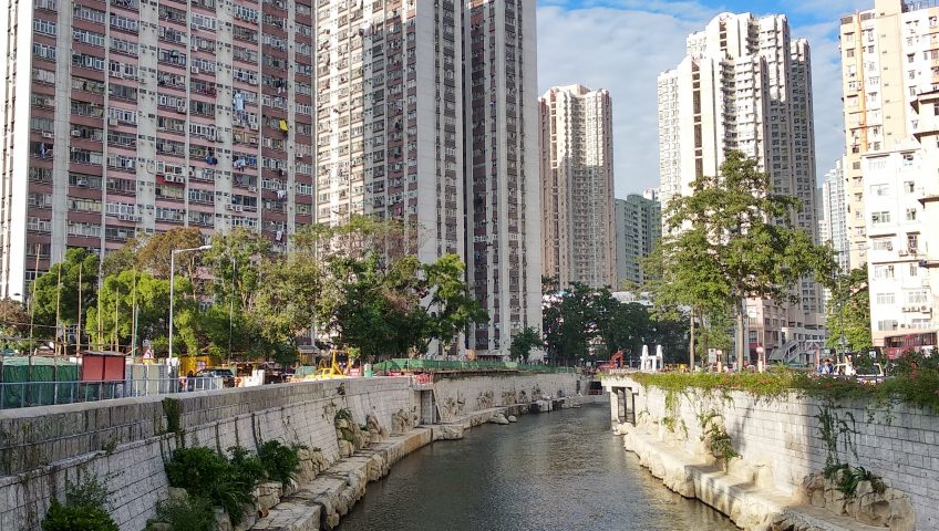
While a lot of resources have been allocated to MiC , Transitional housing and New town development , we can see there are some abandoned or under-utilised space in urban area , which can be converted into the habitation purpose. We have attempted successfully such conversion in some old districts in Hong Kong. We hope we can bring more similar cases for sharing in future


Click here to know more about building defects!

There is always an indispensable relationship between buildings defects, structural stability, and public health. In general, non-structural cracks, structural cracks, concrete spalling, defective external wall finishes and water seepage, etc can be the common types of building defects, which can be easily found in buildings in which do not receive proper maintenance and repair.
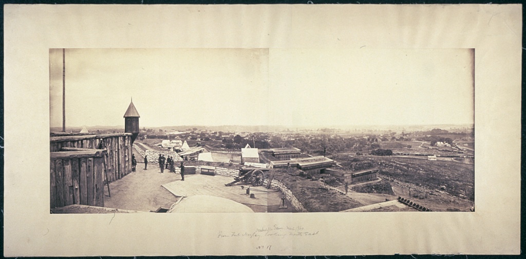
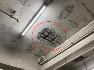
Photo showing concrete spalling from the ceiling

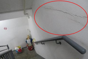
Photo showing cracks inside staircase

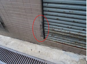
Photo showing concrete spalling

Photo showing external wall tiles was found missing

Today, as a surveyor graduate trainee, I want to share some causes for the development of building defects. There can be a combination of factors in causing the above-mentioned defects. All property will face some sort of defects during its life span. As a surveyor graduate trainee, we shouldn’t solely focus on the physical look of building defects, we need to observe the surrounding environment and the actual usage in concluding the cause of the particular building defects.

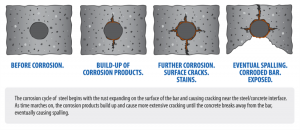
Design, material, construction, usage, and maintenance are the common angles in diagnosis the causes of defects. Taking concrete spalling as one of the examples, given the design stage, when the building is located near the sea, the chloride attack raised from the sea may corrode the steel bar. With the corrosion of the rebar, the volume of rebar inside the concrete will expand 8 times. Crack and concrete spalling may be found.   At the same time, concerning the construction stage, the high water-cement ratio may bring void for the concrete surface due to the increase in permeability, which has the potential possibility to enhance the corrosion of rebar (you can refer to the blog from GBE dated on 28 June 2020). From the above reasons, we understand that the building defects may not be caused by a single reason only. It is the responsibility of the professional to conduct a detailed building inspection before jumping to a conclusion.

Photo showing the stage of rebar corrosion (retrieved from structural engineering blog)

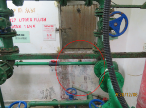
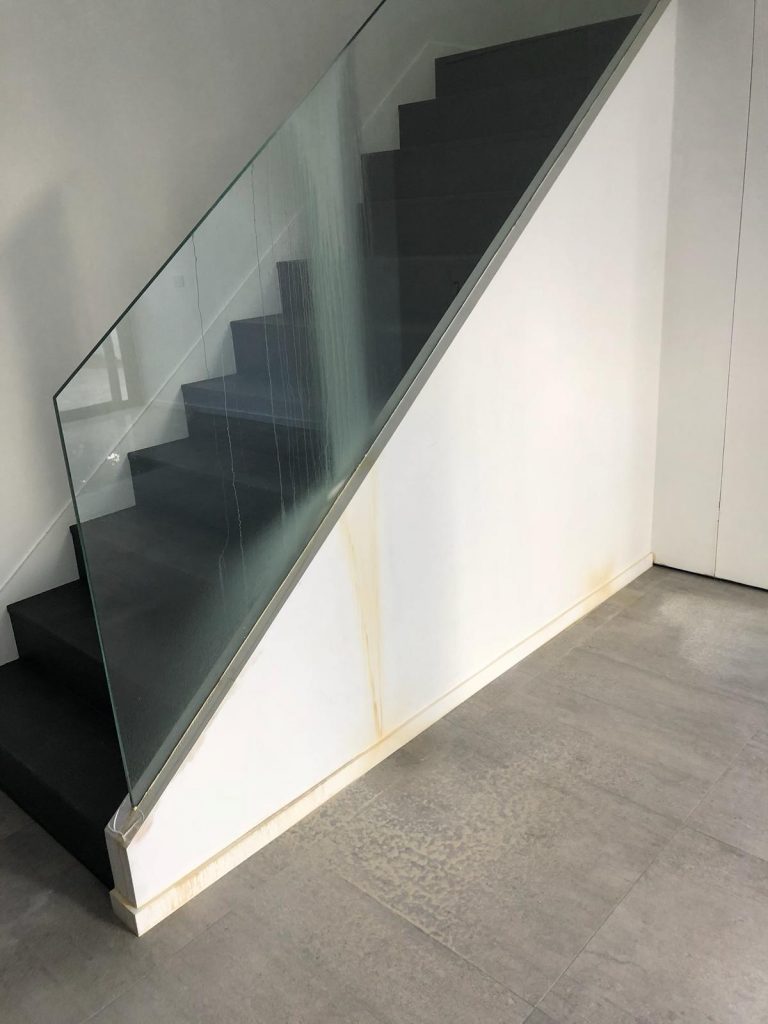
Water Seepage is also a common building defect in aged buildings. The sources of water may come from rain, groundwater, element, condensation, plumbing, drainage, and user activities. When we observe some symptoms like water stains, water dripping, rusty stains, peeling of paint during the inspection, suspected water seepage maybe happened. Before diagnosing the source of water seepage, a preliminary desk study is required (if you wanna know about the details of desk study in how to tackle the annoying issue comes from water dripping in the living area, you mustn’t miss the blog from GBE dated on 4 Jan 2021). We may need to collect some background information like the location of dampness, the frequency of occurrence, the extent of the dampness, repair record, any complaints on the water seepage in identifying the source of such dampness. Visual Inspection and some testing tools like moisture mete can be applied in determining the source of seepage. In some cases, where we suspected the water seepage was caused by the defective waterproofing membrane from the upper unit or roof, a water ponding test may be adopted. At the same time, when we suspected the water dampness was raised by the leakage of the plumbing pipe, a meter test can be adopted in deterring the actual source of such seepage.

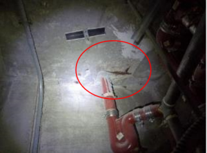
Photo showing a suspected case of water seepage

In order to maintain a safe and healthy environment for occupants, routine inspection, repair works, and maintenance works are suggested to carry out in every building.

Misery water seepage sources – Annoying water dripping in the middle of living area

Again , again and again, the water seepage investigation demands a highly complex analysis to both in-situ environment and desk study. The case presented here has been left unresolved over 2 years before GBE was called on board and finally took the issue to the end.


The annoying water dripping in middle of living area.

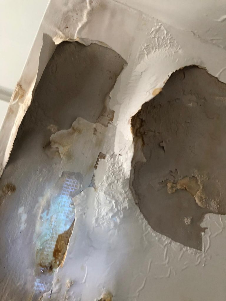
The building is a 4 storey house. It is generally deemed a luxury town house in Hong Kong. A water damp appeared on the ceiling of ground level where is the living area for family gathering. The damp worsened onward and started water dripping everytime the heavy rainfall happened. The seepage spot is about 8m away from the external wall. It became very misery where the water came.

Don’t undermine the importance of desk study 

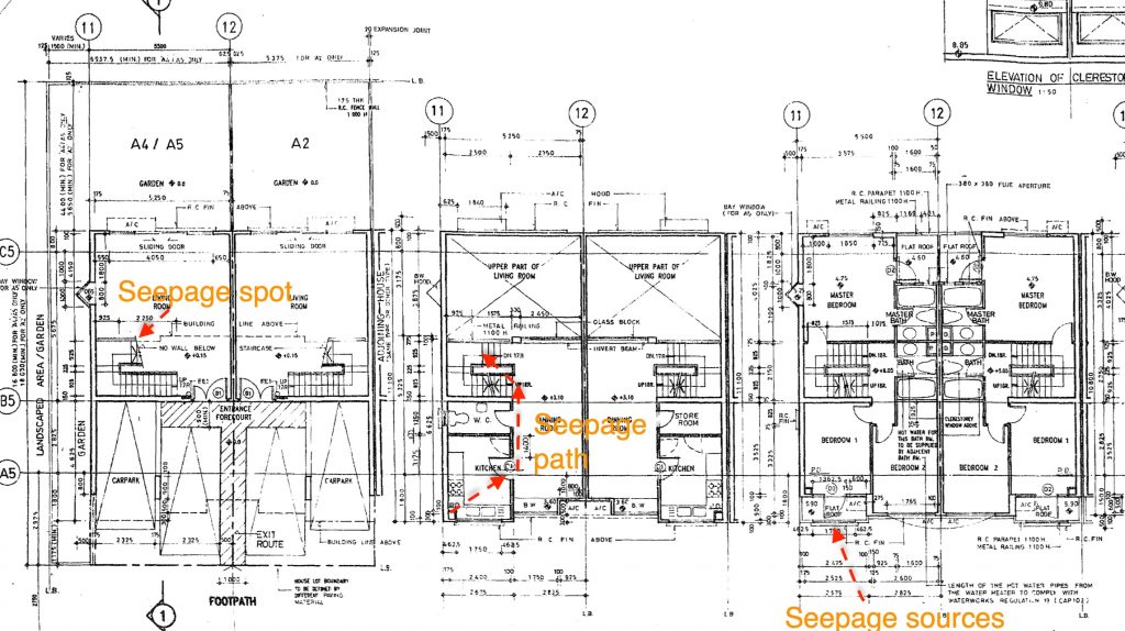
Having reviewed the layout plan, structural plan, decoration record photos and some maintenance history, we have considered a few possible sources which might be attributed to the water seepage. Following with the desk study, we took the site inspection firstly to verify the information obtained from desk study, to survey any other information which were not found in desk study. This really demanded a lot of professional call because those items outside the desk study were also very tricky.

Patient is important – Elimination Method with “Right” Testing

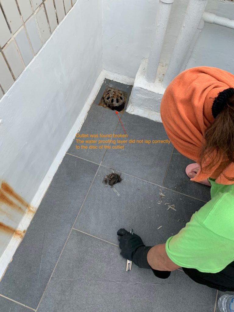
With reference to many literature , the way to identify the water seepage sources is “Elimination”. We have to establish the few possible sources and apply the “Right” testing to verify the assumption. This needs some experience together with the professional judgement. Sometimes , the site condition can render some cues for this judgement. In this case , we have done the survey to window , external wall, roof and some interior fitting out. The condition of window suggested its good and fair condition while the rain outlet at the roof and the skirting at the roof have found not properly done. We thus started the pooling test to the roof.

Judgement Call for the possible seepage path

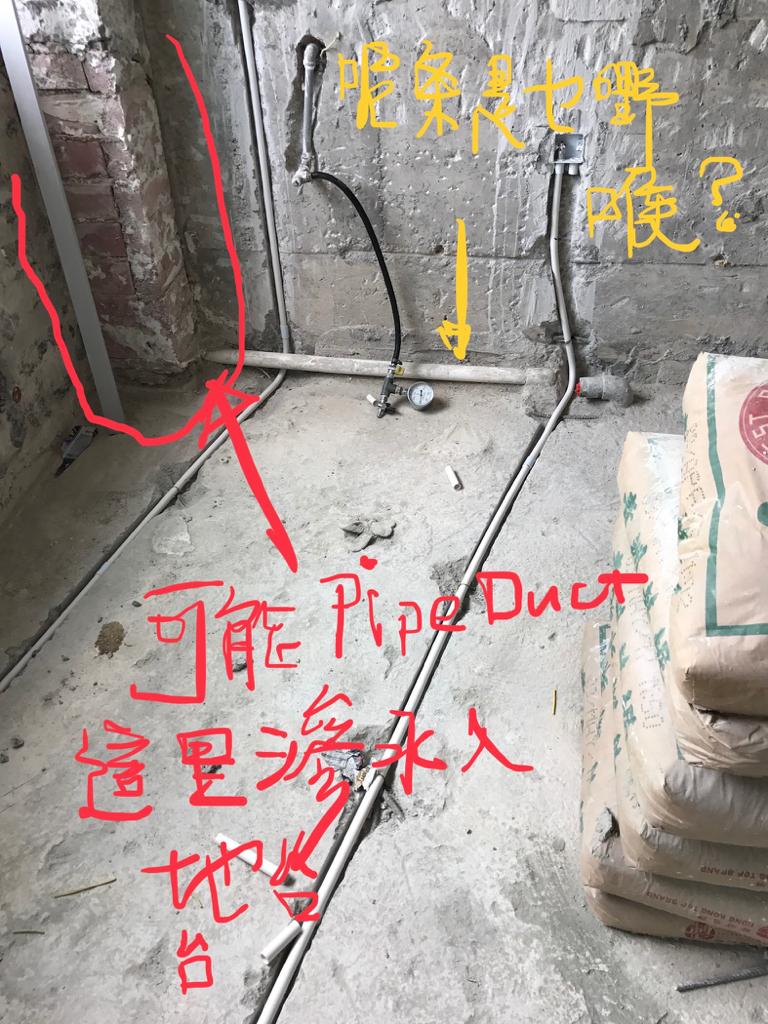
With the aid of fluorescent liquid, the pool of liquid is prepared and stayed for 48 hours. Followed to this , we then applied the UV torch for tracing the “possible path” . Again, the “possible path” demanded a lot of imagination , but we found the cues in the record photos. We found that the conduit were laid in the recessed chase formed on the floor level. It could be pathway for water running.

.


We found the seepage and fix it 

Visual Information Technology in Surveying and Engineering Industries – Part 1

Visual information is always the most direct way for human beings to understand and explore the world. In the past, human beings used drawings for recording history and details. All this visual information can help people nowadays to understand the information and imagine the visual world.

Image is one of the most important records in both surveying and engineering which used for monitoring the progress and review the findings throughout site inspection. More photo records which will help to indicate more details refer to the drawings. Therefore, a good practice of site inspection; photos taking is always a key factor which may affect the progress and follow up actions for all projects.

Importance of Visual Information

According to “YourStory”, humans are wired to respond to visuals more than just text. As visual content is easier to consume and digest.

  • Around 50-80 percent of the human brain is dedicated to visual processing such as vision, visual memory, colours, shapes, movement, patterns, spatial awareness, and image recollection. (Reports The Wiley Network)
  • Visuals with colour increase people’s willingness to read a piece of content by 80 percent. (Reports – Saurage Research)
  • If you hear a piece of information, you might remember only 10 percent of it. Adding a picture to that results in a rise of recall up to 65 percent. (Source – Brainrules.net)
  • Posts inclusive of images produce 650 percent higher engagement than text-only posts. (Source – Pinterest)
  • It takes only 150 milliseconds for us to a process and image, and then another 100 milliseconds for us to attach any meaning to it. (Reports – Canva)
  • People following directions with text and illustrations do 323 percent better than people following directions without illustrations. (Source – Pinterest)

Credit: https://yourstory.com/2018/04/scientific-reasons-visual-marketing?utm_pageloadtype=scroll

Credit: http://www.iscribblers.com/infographics/5-scientific-reasons-people-are-wired-to-respond-to-visual-marketing/

From Drawings to Photography

As visual information is so important for humans in learning process. Our ancient used drawings to record the history since stone age which helps us to understand the past.

Credit: https://vestnikkavkaza.net/upload2/2017-01-13/180b9ee15b8c4384cd6b36e2cd51c377.jpg

Panoramic drawings become more popular which gave people a great impression for easier understand the information that painter want to deliver. Famous panoramic drawings can be found worldwide, such as “Along The River During the Qingming Festival” (China), Barker’s London panorama of 1792, from the top of the Albion Mills (UK).

Credit: https://upload.wikimedia.org/wikipedia/commons/d/d9/Panorama_of_London_Barker.jpg

Credit: https://www.youtube.com/watch?v=mwMwDYEfMy0&feature=youtu.be

Drawing is a good source of visual information that can record the moment and reflect the details; however, drawings completion may lead a long time to complete and all details are from painters’ memory only.

Photo is another good source for recording and faster in the workflow. Photography technology and also computer software have been developed into a next-generation which help all stakeholders to study and learn deeply with site situation. Location, time, measurement information are also be able to capture by today’s technology.

In the past, film cameras are used for photo taking which will be limited due to cost and photography skills by the site staff. Most photos taking will be either whole shot and defects, not enough details can be shown in those photos.  Since photography technology has been improved a lot, the digital camera has taken the industry practice to the next generation. In the same situation with drawings, people always want to take more details in one shot in order to show more information and surrounding.

A panoramic view of the construction of the ESO Supernova Planetarium & Visitor Centre.

Credit: Architekten Bernhardt + Partner (www.bp-da.de)

With the aid of technology, split-screen panoramic photo comparison enables remote stakeholders to check and communicate with each other remotely in the same platform. Such technology can resolve conflicts and misunderstandings during the construction process. Those photo records can also be stored for facilities management to use for repair and maintenance purposes.

In the next chapter, we will go through more new technologies to show how the new cameras can help in site inspection and measurement.


Make Use of Verandah in High Rise Buildings for Fire Safety Aspect

The impact of Fire Safety Code in Hong Kong

The fire safety code has experienced a few rounds of reform. The most influential reform we opined was the code published in 1996 and also the code in 2011. While there are many honorable peers have shared the view to both code applicable in Hong Kong, GBE found one interesting HK-unique escape staircase arrangement which have been prevailing in 2 decades ago. This the verandah space intercepting between the apartment units and the requirement staircase (usually scissor-type)


Verandah Space being merged 

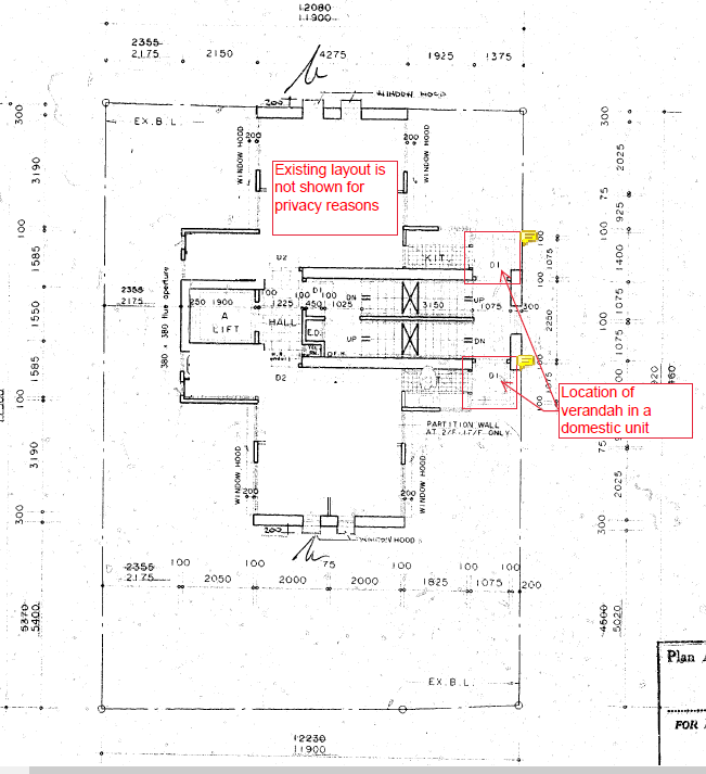
This verandah space was a space designed in half-open to the external air. The space is connecting between the staircase and the apartment unit through the fire-rated doors. Driven by congested space in Hong Kong, some verandah, in this case, has been enclosed by the window and merged to the apartment units. This was deemed to be against the fire safety code or approved plan.


GBP for showing the Typical location of the verandah in a domestic unit

The Provision of HK CAP 502

In 2007, the HONG KONG CAP 572 Fire Safety (Buildings) Ordinance has been put into enforcement. The “Purpose Of Ordinance” is cited in clause 2 of Cap 572 and We copied here as follows.

This ordinance is aimed to provide protection from the risk of fire of occupants, users, and visitors to certain kinds of composite buildings and domestic buildings.

The law further explains the requirements including fire service installation and equipment and fire safety construction for different kinds of buildings in its Schedule 1 , 2, and 3 correspondingly. The governing requirements stated clearly is to apply the Code 1996 as the “standard” to satisfy the intention of this Ordinance. Thus, the said “Verandah” enclosure or modification is likely in this radar.


What did Code in 1996 talk about the “Verandah”

In our view, there was no direct elaboration to the “veranda” being designed for the intercepting lobby between the required staircase and the unit. From the MOE code 1996 and FRC 1996, there was a few relevant paragraphs which came up eventually the “veranda” application as a protected lobby. Since the author was not the Code writer nor in an authoritative position to comment, this blog of write-up serves to trigger some interesting discussion.


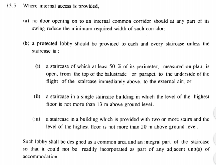
The provision of the “Protection” lobby was written in clause 13.5 in MOE 1996 and the design of “Protection lobby” was explained in 11.3 FRC 1996. Nevertheless, the enclosing wall of the Protected lobby was further explained in clause 11.7. Honestly, it was a complex integration of different clauses at different code and could easily lead to various explanation outcomes. This undesirable situation such complex set of codes has been improved in lately 2011 code.

The interpretations of Protected Lobby stated in MOE 1996 Code

The design of “Required staircase and protected lobby” was explained in Clause 11.3 at FRC 1996 Code

The Clause 13.5 in MOE 1996 Code

Indeed, the old 1996 code has remarked very clearly in clause 13.5 MOE 1996 code that “such lobby shall be designed as a common area and an integral part of the staircase so that it could not be readily incorporated as part of any adjacent unit(s) of accommodation” The 1996 code did aware the issue of merging the protection lobby to the private unit. Nevertheless, the complex nature of the set of codes 1996 which led to different explanations may undermine the intention in clause 13.5.

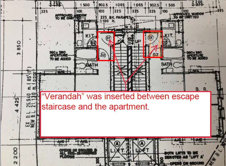
Plan for demonstrating the Verandah between the required staircase and the apartment

Above is another example where the “Veranda” was inserted between the escape staircase and the apartment. Interestingly, the kitchen doors also opened to the verandah. It was believed that this layout configuration is hardly survivable in today’s Code.

“Common Staircase” shared by adjoining lot in Hong Kong

The leftover structure coming from rapid Urban redevelopment in Hong Kong

In the urban development , the land was delineated by “Block” and was subsequently craved or partitioned in a different section and eventually further craved into different sub-section. It resulted a lot of common boundary to each piece of lands adjoining to each other.


The common boundary bought in the typical implication of “party wall” and “common staircase”. There was a blog written by GBE about “party wall”. The reader is welcome to comment. “Common staircase” is what this article goes deep.


The main staircase of the building became as “common” because it was commonly shared between two pieces of land. The common staircase was jointly owned for the enjoyment of the entire building. Since it was common to two adjoining pieces of land, it naturally positioned at the boundary line. It was not a must but naturally came up in the middle between two lots.

Redevelopment and remaining common staircase

With the re-development took place in one piece of land, the adjoining land where the original main building sitting on was necessitated to maintain the common staircase for access. This came up the situation alike to the “Party wall” where the common staircase needs to be retained and still occupy land and space on the land going to be redeveloped.


The first and immediate concern is obviously the common staircase is an enclosed space and fall into the definition of GFA. Nevertheless, this common staircase is nothing helpful and undesirable to new development. To cope with this, the above-extracted part plan has illustrated the example of how the PNAP ADM -2 resolves the GFA problem. In short , the entire footprint of the common staircase be deductible from the GFA calculation. According to PNAP ADM-2 from the Buildings Department, the existing common staircase for an old building can be excluded from site coverage and plot ratio calculation.


Case Study in two adjoining Urban buildings

Building “A” was redeveloped in 1992. The landlord was obligated to leave the common staircase un-touched and exempted its footprint from accountable GFA. Building “B” was subsequently redeveloped in 2008, but the redevelopment of Building B has demolished partly the “common staircase” sitting on the respective piece of land.

Ground Floor Plan of Building A (showing the Location of Common staircase with Building B)


GFA Calculation of Building A


Ground Floor Plan of Building B (showing the Location of Common staircase with Building A)


Site Area Calculation in Building B

Another example showing the common staircase issue

Building “C” was redeveloped in 2004, while Building D was redeveloped in 1994. Building “C” and Building “D” retained the common staircase after both redevelopments.

Ground Floor Plan of “Building C”

Ground Floor Plan of “Building D”

Funny interesting maintenance issue

The interesting things come up is that building A which developed earlier than Building B was containing the old “common staircase” . This old left-over common staircase in Building “A” was not GFA counted by the time of redevelopment. The owner of Building A is caught in dilemma. The site where building A sitting on has fully exploited its GFA potential by the time of its redevelopment in 1992. It is now found no surplus GFA be able to assign to this leftover physical ” common staircase” space in the hope to light up again the space utilisation, particularly valuable in highly urbanised city area. The landlord of building A is naturally no incentive to maintain nor convert this common staircase to other proper usage. The only value is the external wall of the left-over common staircase which was being poised for signage in Building “A” (as shown on the photo below. Obviously, the author is wondering the maintenance liability to the grandfather jointly owned structure , i.e Common staircase


Misery of Non-accountable GFA in Existing Building. The road from plain drawings to value-added

GFA is the core asset in real estate

GFA – Gross Floor Area is considered as the core valuable asset in real estate. One of the significant governing regulation to GFA stated in Buildings Ordinance is Building (Planning )Reg 23. The Reg 23 (3)(b) have listed in literal form the areas which can be subject to non-accountable GFA whereas the Reg 23(3)(a) has included all areas within the external of buildings as GFA countable.

The Ordinance allows some accountant GFA in 23(3)(a) becomes considered as non-accountable GFA through the power vested to Buildings Authority by section 42 of Buildings Ordinance and explained by the ADV – 02 (PNAP 30 in former version). Some GFA calculation cases are further complicated by the injection of sustainable development requirements stated in APP 151.

Existing Building GFA vs Regulation 23(a) 

In existing Building which was built in decade ago plus , the control to the non-accountable GFA was relied by Reg 23(3)(b) which generally covered the essential plants / duct / carpark etc. When the landlord wants to review/revamp the existing GFA hoping for unlocking the hidden potential, the latest requirements in 23(3)(a) mentioned before will kick in to the backdrop.

Some areas within the building which had been exempted from accountant GFA in the past may have to re-examine under Reg 23(3)(a) and is assessed in the ADV -02. The interesting but painful point is that some typically exempted in the past may now become accountable unless the modification is granted by BA. In some case, the modification is not straight-forward but under complex assessment such as BEAM requirement in APP 151. Obviously, the latest GFA requirements has blocked the unlock of some potential GFA.

Example showing the effect impact from tightening of GFA assessment

Assuming there is plant room , this plant room is assumed be acceptable by Reg 23(b). The implication of GFA will be manifest because the protected lobby going with the plant room will be exempted. To the contrary, If the said “plant room” is NOT in Reg 23(b), the GFA exemption will be at the stakes. The wall and associated protected lobby solely serving for plant rooms will be subject to the “non-mandatory features”. The area of wall and associated protected lobby will be barred by the overall cap of 10% in paragraph 4 APP 151 for non-mandatory features) . The capping 10% will effect some GFA from non accountable back to accountable.

Case by Case assessment 

Valuable assets in the urban areas are all GFA driven for the best maximization of property value. This is the key driving incentive to closely review and revamp from time to time to unlock the potential hidden GFA in the active asset management.

(Reader is advised to look also other strategies which have been shared in our other blog” of this website)


EV Parking vs Additional FSI

Demand for EV Charger facilities in existing (old) building carpark is definitely rising in the town. Many would focus on reliability of new power consumption, enhancement of infrastructure and how best to house those new facilities. In GBE, fire safety with respect to the additional fire load of EV charger facilities is also our key consideration on design and planning of project. Incorporation of smoke detection system, fire extinguisher, Direct Link connection and Fireman’s emergency switch, etc. are encouraged for the relevant project. Enhancement of client’s assets and upholding of high level of safety are one of our major deliverable to our clients.

Part 2 : Coating materials for Aluminium cladding – Misery of “Self-cleaning”

Following with our part 1 discussion, we now share another hot topic about coating applied on the aluminium. “Self-cleaning” is indeed a merchants’ name . The behind sciences are varying from among different manufacturer. We have conducted some comparison among different materials being applied to the cladding surface.

Theory of “Self-cleaning”

Self-cleaning : Hydrophilic approach 

In short, there are a few theories behind the “self-cleaning” . One typical approach is to create the surface which reduce the water surface tension. When the water droplet lands on the surface, the water droplet has formed an wetting angle to the surface of cladding. The stronger the water tension, the more acute the wetting angle is. The below diagram explains the wetting angle and how it carries the dirt / stain / attachment on the surface. Different manufacturer has formulated different chemical materials to reduce the water tension and flatten the wetting angle. The water is to carry and flush away the dirt. The most typical chemical approach is to create the coating surface which offer better hydrophilic (hydrophilic is origin from latin word, the word philic means love).


Self-cleaning : Photo-catalytic Oxidation 

Another theory is by “Photo-catalytic Oxidation” . We are not Chemist and cannot cite the theory . Nevertheless, we found one extract from “Chemosphere 193( 2018-198-206)” ,  there explains the “photo-catalytic oxidation” with the below graphic. In short, it is the oxidation process to the VOCs by UV and Photon. This is again alleged by many peers as ” self – cleaning” , but obviously the theory is very different from “hydrophilic approach”

Self-cleaning : Hydrophilic approach

To the contrary of “Hydrophilic” , some manufacturer applied the opposite ; hydrophobic approach. The theory behind is to keep the strong water tension of the droplet and let the droplet to “PICK” the dirt away. From our very preliminary scanning , this technique was more relying on the water – repellent nature ,

Product in the market : – 

We have encountered different approaches in the market. All suggest their “self-cleaning” properties. We try to cite some examples to illustrate different theory behind . We are not in the position to comment each performance and indeed it is difficult to do comparison. We hope this articles can offer some ideas for future research

Kansai Paint : 

One of the product is made by Kasiai, we were given the understanding that the materials is silicon-based modified resin materials with their own additive untold to the public. This is to create the “Hydrophilic” by flush and deliver the dirt.


Hydrotech from TOTO

Hydrotect is the tradename by TOTO. We extract their self-allegation from their official website. In short, they claimed their coating technique is photocatalytic which is to OXIDE the VOCs in the air. Their website further suggests this “Hydrotect” can offer the hydrophilic surface to flush the dirt

XX Sheet film paper 

A manufacturer , named to be untold here, claimed that there film sheeting offer the self-cleaning. We cannot identify their theory online. Nevertheless, we did a quick water spray test on the surface. We noticed that the water droplet kept intact on the surface and did not appear wetting pattern which is for flushing the surface.  From the picture below, the water – droplet keeps visually keeps the sharp and the droplet drip pattern is in the form of line.


Fire Safety in Commercial Premises

Fire safety can be regarded as one of the primary considerations in building designs. The terms of fire safety cover a wide range of building concepts, ordinances, and regulations under the law. When we consider the fire safety works in banks, the concept of Fire Safety (Commercial Premises) Ordinance should not be omitted. The introduction of FS(CP)O is one of the ordinances which aims to provide better protection to the occupants and visitors on certain kinds of commercial premises.

Prescribed commercial premises and specified commercial buildings are under the scope of the ordinance.  For the captioned the premise, they are required to update that fire safety construction including means of escape, means of access, fire-resisting construction under the Code of Practice for the Provision of Means of Escape in Case of Fire 1996, Code of Practice for Fire Resisting Construction 1996, Code of Practice for the Provision of Means of Access for Firefighting and Rescue 1995 respectively. Also, the premises required to update fire services installation following Codes of Practice for Minimum Fire Service Installations and Equipment and Inspection, Testing, and Maintenance of Installations and Equipment 1994 when the total floor area exceeds 230 square meters.

As a building professional to cope with the above issue, a desktop study needs to be conducted first. It is essential to calculate the number/width of the exit door and exit route following the purposed usage of the premises. The comparison of the recorded plan and Fire Safety (Commercial Premises) Ordinance may draw attention to the fire safety deficiencies. The site visit is followed to identify the deficiencies. fire services system always associates with water supplies and electricity. For the aged building, some non-emergency services like electricity will be located in the exit route. However, those non-emergency services did not enclose by FRR materials. It may post a potential fire hazard. Insufficient width of the MOE route, insufficient number of exit routes to the required staircase, presence of the fire shutter in the exit route, absence of exit sign, absence of the exit door, etc are the common scenario for the aged commercial premises to deal with the ordinance. The reasons for the above deficiency can be caused by certain reasons including the change in use, the absence of the fire safety ordinance during the construction period, and unauthorized building works by the owners.