Misery water seepage sources – Annoying water dripping in the middle of living area

Again , again and again, the water seepage investigation demands a highly complex analysis to both in-situ environment and desk study. The case presented here has been left unresolved over 2 years before GBE was called on board and finally took the issue to the end.


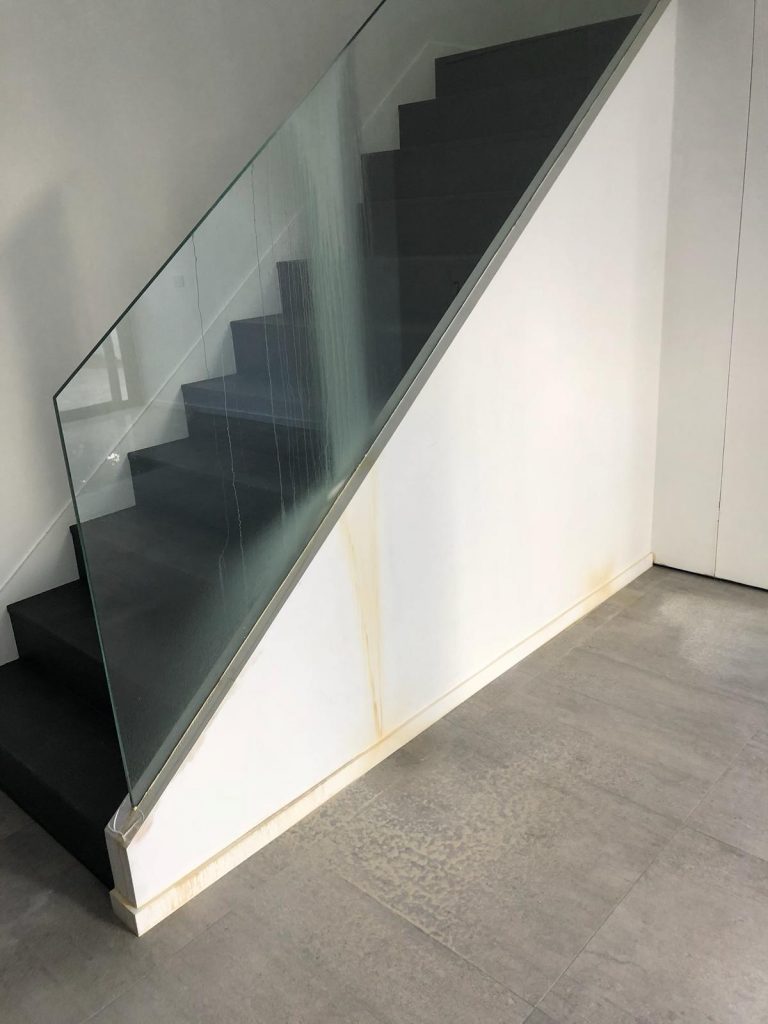
The annoying water dripping in middle of living area.

The building is a 4 storey house. It is generally deemed a luxury town house in Hong Kong. A water damp appeared on the ceiling of ground level where is the living area for family gathering. The damp worsened onward and started water dripping everytime the heavy rainfall happened. The seepage spot is about 8m away from the external wall. It became very misery where the water came.

Don’t undermine the importance of desk study 

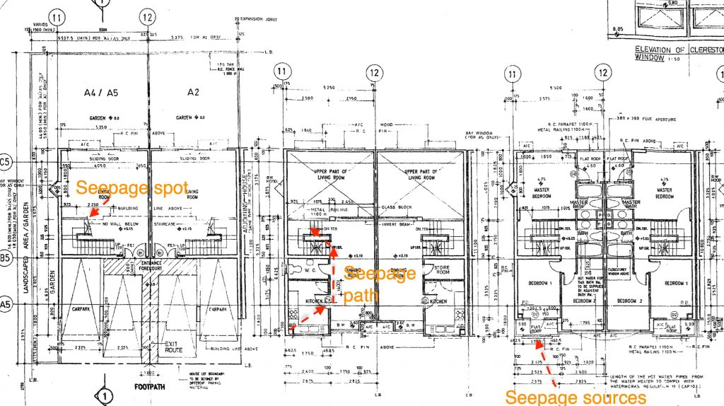
Having reviewed the layout plan, structural plan, decoration record photos and some maintenance history, we have considered a few possible sources which might be attributed to the water seepage. Following with the desk study, we took the site inspection firstly to verify the information obtained from desk study, to survey any other information which were not found in desk study. This really demanded a lot of professional call because those items outside the desk study were also very tricky.

Patient is important – Elimination Method with “Right” Testing

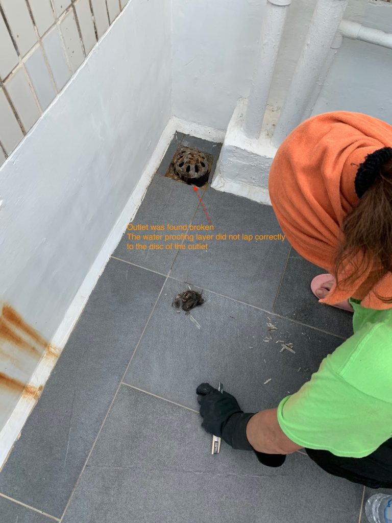
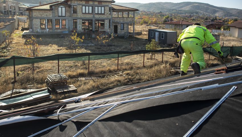
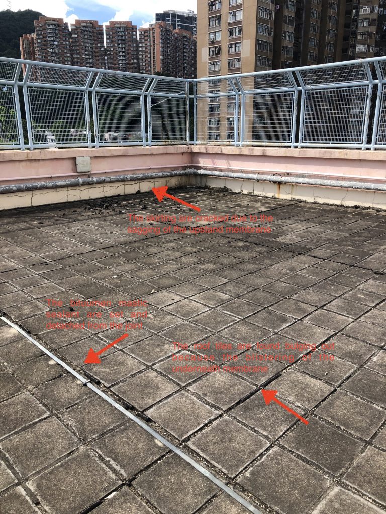
With reference to many literature , the way to identify the water seepage sources is “Elimination”. We have to establish the few possible sources and apply the “Right” testing to verify the assumption. This needs some experience together with the professional judgement. Sometimes , the site condition can render some cues for this judgement. In this case , we have done the survey to window , external wall, roof and some interior fitting out. The condition of window suggested its good and fair condition while the rain outlet at the roof and the skirting at the roof have found not properly done. We thus started the pooling test to the roof.

Judgement Call for the possible seepage path

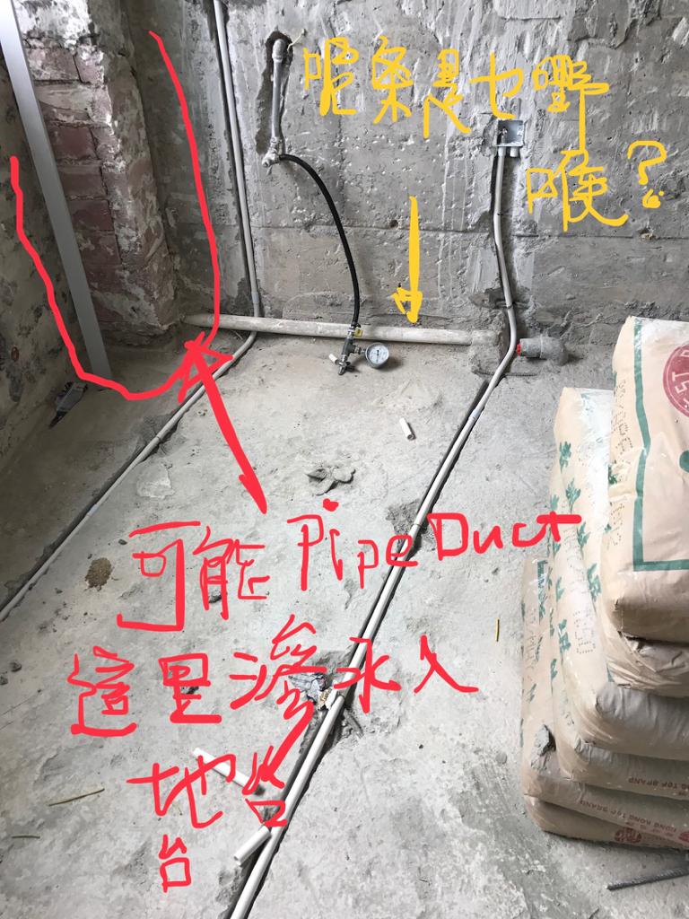
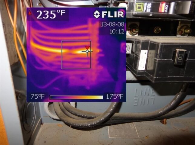
With the aid of fluorescent liquid, the pool of liquid is prepared and stayed for 48 hours. Followed to this , we then applied the UV torch for tracing the “possible path” . Again, the “possible path” demanded a lot of imagination , but we found the cues in the record photos. We found that the conduit were laid in the recessed chase formed on the floor level. It could be pathway for water running.

.


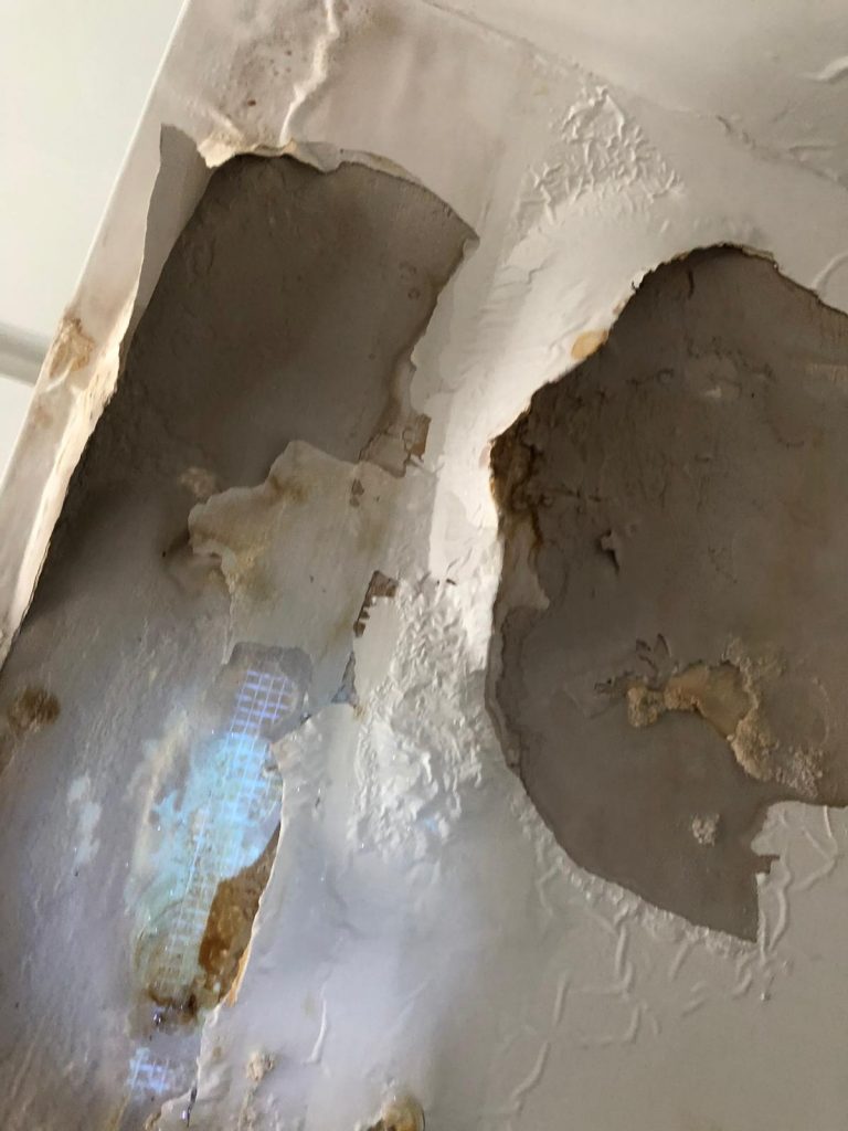
We found the seepage and fix it 

Make Use of Verandah in High Rise Buildings for Fire Safety Aspect

The impact of Fire Safety Code in Hong Kong

The fire safety code has experienced a few rounds of reform. The most influential reform we opined was the code published in 1996 and also the code in 2011. While there are many honorable peers have shared the view to both code applicable in Hong Kong, GBE found one interesting HK-unique escape staircase arrangement which have been prevailing in 2 decades ago. This the verandah space intercepting between the apartment units and the requirement staircase (usually scissor-type)


Verandah Space being merged 

This verandah space was a space designed in half-open to the external air. The space is connecting between the staircase and the apartment unit through the fire-rated doors. Driven by congested space in Hong Kong, some verandah, in this case, has been enclosed by the window and merged to the apartment units. This was deemed to be against the fire safety code or approved plan.


GBP for showing the Typical location of the verandah in a domestic unit

The Provision of HK CAP 502

In 2007, the HONG KONG CAP 572 Fire Safety (Buildings) Ordinance has been put into enforcement. The “Purpose Of Ordinance” is cited in clause 2 of Cap 572 and We copied here as follows.

This ordinance is aimed to provide protection from the risk of fire of occupants, users, and visitors to certain kinds of composite buildings and domestic buildings.

The law further explains the requirements including fire service installation and equipment and fire safety construction for different kinds of buildings in its Schedule 1 , 2, and 3 correspondingly. The governing requirements stated clearly is to apply the Code 1996 as the “standard” to satisfy the intention of this Ordinance. Thus, the said “Verandah” enclosure or modification is likely in this radar.


What did Code in 1996 talk about the “Verandah”

In our view, there was no direct elaboration to the “veranda” being designed for the intercepting lobby between the required staircase and the unit. From the MOE code 1996 and FRC 1996, there was a few relevant paragraphs which came up eventually the “veranda” application as a protected lobby. Since the author was not the Code writer nor in an authoritative position to comment, this blog of write-up serves to trigger some interesting discussion.


The provision of the “Protection” lobby was written in clause 13.5 in MOE 1996 and the design of “Protection lobby” was explained in 11.3 FRC 1996. Nevertheless, the enclosing wall of the Protected lobby was further explained in clause 11.7. Honestly, it was a complex integration of different clauses at different code and could easily lead to various explanation outcomes. This undesirable situation such complex set of codes has been improved in lately 2011 code.

The interpretations of Protected Lobby stated in MOE 1996 Code

The design of “Required staircase and protected lobby” was explained in Clause 11.3 at FRC 1996 Code

The Clause 13.5 in MOE 1996 Code

Indeed, the old 1996 code has remarked very clearly in clause 13.5 MOE 1996 code that “such lobby shall be designed as a common area and an integral part of the staircase so that it could not be readily incorporated as part of any adjacent unit(s) of accommodation” The 1996 code did aware the issue of merging the protection lobby to the private unit. Nevertheless, the complex nature of the set of codes 1996 which led to different explanations may undermine the intention in clause 13.5.

Plan for demonstrating the Verandah between the required staircase and the apartment

Above is another example where the “Veranda” was inserted between the escape staircase and the apartment. Interestingly, the kitchen doors also opened to the verandah. It was believed that this layout configuration is hardly survivable in today’s Code.

“Common Staircase” shared by adjoining lot in Hong Kong

The leftover structure coming from rapid Urban redevelopment in Hong Kong

In the urban development , the land was delineated by “Block” and was subsequently craved or partitioned in a different section and eventually further craved into different sub-section. It resulted a lot of common boundary to each piece of lands adjoining to each other.


The common boundary bought in the typical implication of “party wall” and “common staircase”. There was a blog written by GBE about “party wall”. The reader is welcome to comment. “Common staircase” is what this article goes deep.


The main staircase of the building became as “common” because it was commonly shared between two pieces of land. The common staircase was jointly owned for the enjoyment of the entire building. Since it was common to two adjoining pieces of land, it naturally positioned at the boundary line. It was not a must but naturally came up in the middle between two lots.

Redevelopment and remaining common staircase

With the re-development took place in one piece of land, the adjoining land where the original main building sitting on was necessitated to maintain the common staircase for access. This came up the situation alike to the “Party wall” where the common staircase needs to be retained and still occupy land and space on the land going to be redeveloped.


The first and immediate concern is obviously the common staircase is an enclosed space and fall into the definition of GFA. Nevertheless, this common staircase is nothing helpful and undesirable to new development. To cope with this, the above-extracted part plan has illustrated the example of how the PNAP ADM -2 resolves the GFA problem. In short , the entire footprint of the common staircase be deductible from the GFA calculation. According to PNAP ADM-2 from the Buildings Department, the existing common staircase for an old building can be excluded from site coverage and plot ratio calculation.


Case Study in two adjoining Urban buildings

Building “A” was redeveloped in 1992. The landlord was obligated to leave the common staircase un-touched and exempted its footprint from accountable GFA. Building “B” was subsequently redeveloped in 2008, but the redevelopment of Building B has demolished partly the “common staircase” sitting on the respective piece of land.

Ground Floor Plan of Building A (showing the Location of Common staircase with Building B)


GFA Calculation of Building A


Ground Floor Plan of Building B (showing the Location of Common staircase with Building A)


Site Area Calculation in Building B

Another example showing the common staircase issue

Building “C” was redeveloped in 2004, while Building D was redeveloped in 1994. Building “C” and Building “D” retained the common staircase after both redevelopments.

Ground Floor Plan of “Building C”

Ground Floor Plan of “Building D”

Funny interesting maintenance issue

The interesting things come up is that building A which developed earlier than Building B was containing the old “common staircase” . This old left-over common staircase in Building “A” was not GFA counted by the time of redevelopment. The owner of Building A is caught in dilemma. The site where building A sitting on has fully exploited its GFA potential by the time of its redevelopment in 1992. It is now found no surplus GFA be able to assign to this leftover physical ” common staircase” space in the hope to light up again the space utilisation, particularly valuable in highly urbanised city area. The landlord of building A is naturally no incentive to maintain nor convert this common staircase to other proper usage. The only value is the external wall of the left-over common staircase which was being poised for signage in Building “A” (as shown on the photo below. Obviously, the author is wondering the maintenance liability to the grandfather jointly owned structure , i.e Common staircase


Misery of Non-accountable GFA in Existing Building. The road from plain drawings to value-added

GFA is the core asset in real estate

GFA – Gross Floor Area is considered as the core valuable asset in real estate. One of the significant governing regulation to GFA stated in Buildings Ordinance is Building (Planning )Reg 23. The Reg 23 (3)(b) have listed in literal form the areas which can be subject to non-accountable GFA whereas the Reg 23(3)(a) has included all areas within the external of buildings as GFA countable.

The Ordinance allows some accountant GFA in 23(3)(a) becomes considered as non-accountable GFA through the power vested to Buildings Authority by section 42 of Buildings Ordinance and explained by the ADV – 02 (PNAP 30 in former version). Some GFA calculation cases are further complicated by the injection of sustainable development requirements stated in APP 151.

Existing Building GFA vs Regulation 23(a) 

In existing Building which was built in decade ago plus , the control to the non-accountable GFA was relied by Reg 23(3)(b) which generally covered the essential plants / duct / carpark etc. When the landlord wants to review/revamp the existing GFA hoping for unlocking the hidden potential, the latest requirements in 23(3)(a) mentioned before will kick in to the backdrop.

Some areas within the building which had been exempted from accountant GFA in the past may have to re-examine under Reg 23(3)(a) and is assessed in the ADV -02. The interesting but painful point is that some typically exempted in the past may now become accountable unless the modification is granted by BA. In some case, the modification is not straight-forward but under complex assessment such as BEAM requirement in APP 151. Obviously, the latest GFA requirements has blocked the unlock of some potential GFA.

Example showing the effect impact from tightening of GFA assessment

Assuming there is plant room , this plant room is assumed be acceptable by Reg 23(b). The implication of GFA will be manifest because the protected lobby going with the plant room will be exempted. To the contrary, If the said “plant room” is NOT in Reg 23(b), the GFA exemption will be at the stakes. The wall and associated protected lobby solely serving for plant rooms will be subject to the “non-mandatory features”. The area of wall and associated protected lobby will be barred by the overall cap of 10% in paragraph 4 APP 151 for non-mandatory features) . The capping 10% will effect some GFA from non accountable back to accountable.

Case by Case assessment 

Valuable assets in the urban areas are all GFA driven for the best maximization of property value. This is the key driving incentive to closely review and revamp from time to time to unlock the potential hidden GFA in the active asset management.

(Reader is advised to look also other strategies which have been shared in our other blog” of this website)


Part 2 : Coating materials for Aluminium cladding – Misery of “Self-cleaning”

Following with our part 1 discussion, we now share another hot topic about coating applied on the aluminium. “Self-cleaning” is indeed a merchants’ name . The behind sciences are varying from among different manufacturer. We have conducted some comparison among different materials being applied to the cladding surface.

Theory of “Self-cleaning”

Self-cleaning : Hydrophilic approach 

In short, there are a few theories behind the “self-cleaning” . One typical approach is to create the surface which reduce the water surface tension. When the water droplet lands on the surface, the water droplet has formed an wetting angle to the surface of cladding. The stronger the water tension, the more acute the wetting angle is. The below diagram explains the wetting angle and how it carries the dirt / stain / attachment on the surface. Different manufacturer has formulated different chemical materials to reduce the water tension and flatten the wetting angle. The water is to carry and flush away the dirt. The most typical chemical approach is to create the coating surface which offer better hydrophilic (hydrophilic is origin from latin word, the word philic means love).


Self-cleaning : Photo-catalytic Oxidation 

Another theory is by “Photo-catalytic Oxidation” . We are not Chemist and cannot cite the theory . Nevertheless, we found one extract from “Chemosphere 193( 2018-198-206)” ,  there explains the “photo-catalytic oxidation” with the below graphic. In short, it is the oxidation process to the VOCs by UV and Photon. This is again alleged by many peers as ” self – cleaning” , but obviously the theory is very different from “hydrophilic approach”

Self-cleaning : Hydrophilic approach

To the contrary of “Hydrophilic” , some manufacturer applied the opposite ; hydrophobic approach. The theory behind is to keep the strong water tension of the droplet and let the droplet to “PICK” the dirt away. From our very preliminary scanning , this technique was more relying on the water – repellent nature ,

Product in the market : – 

We have encountered different approaches in the market. All suggest their “self-cleaning” properties. We try to cite some examples to illustrate different theory behind . We are not in the position to comment each performance and indeed it is difficult to do comparison. We hope this articles can offer some ideas for future research

Kansai Paint : 

One of the product is made by Kasiai, we were given the understanding that the materials is silicon-based modified resin materials with their own additive untold to the public. This is to create the “Hydrophilic” by flush and deliver the dirt.


Hydrotech from TOTO

Hydrotect is the tradename by TOTO. We extract their self-allegation from their official website. In short, they claimed their coating technique is photocatalytic which is to OXIDE the VOCs in the air. Their website further suggests this “Hydrotect” can offer the hydrophilic surface to flush the dirt

XX Sheet film paper 

A manufacturer , named to be untold here, claimed that there film sheeting offer the self-cleaning. We cannot identify their theory online. Nevertheless, we did a quick water spray test on the surface. We noticed that the water droplet kept intact on the surface and did not appear wetting pattern which is for flushing the surface.  From the picture below, the water – droplet keeps visually keeps the sharp and the droplet drip pattern is in the form of line.


Part 1 : Coating materials for Aluminium cladding – Non-Combustibility

From natural anodisation technique to PVF2 coating technique , the aluminium finishing coating has undergone a lot of revolutionary advancement. In recent years, there came with the discussion about “Self-cleaning” of the aluminium coating surface. This is about the coating materials which gives effect to flush its’ surface every time in raining. “Self-cleaning” is indeed a merchants’ name . The behind sciences are varying from among different manufacturer.I have conducted some comparison among some cladding’s surfaces being applied to different “treatment” allegedly claim the self-cleaning properties.  In my small research , some coatings are sheet- applied on the surface of anodised aluminium cladding. Unfortunately, my research (limited online data searching) cannot conclude sheeting-applied one was made up compilable to the Section E clause 10.1 of FS code or as per the BS476 -part 4. Well, many peers have messed up the concept of BS476 – PART 6 / PART 7 which is about spread of fire to BS476 – part 4 which is non-combustibility .


There are some testing to confirm “non-combustibility”. The FS code of Hong Kong does a job to cite a reference table E1 to facilitate the conversion between BS and European standard . There are many building in Hong Kong are cladded with aluminium-panel externally , but the lack of attention is paid to its “non-combustibility” requirement. Example like “self-cleaning” sheet lining or coating or spray-paint applied materials and even the fire – ratardard which are applied on external architectural features. The add-on materials on top of the aluminium are sometimes commercially attractive in term of ease of application and its price but to the sacrifice of fire safety.

Fire accident in Grefell Tower, London

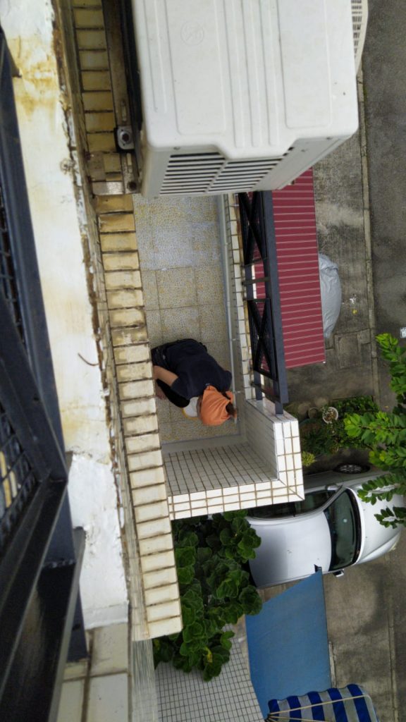
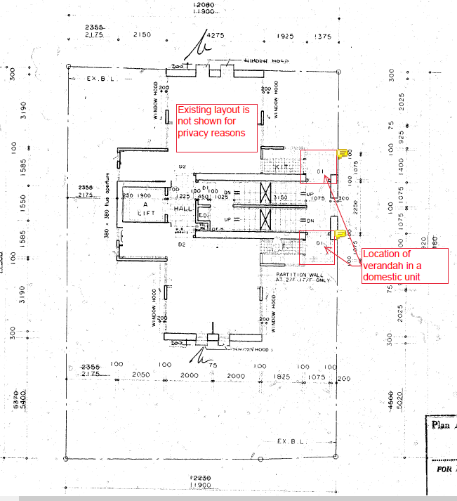
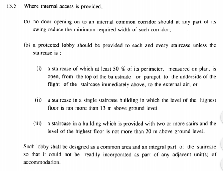
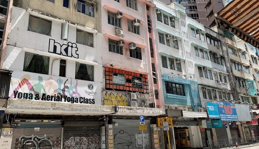
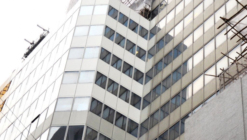
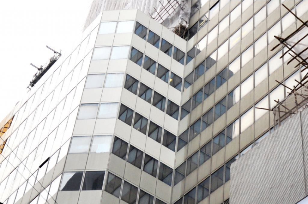
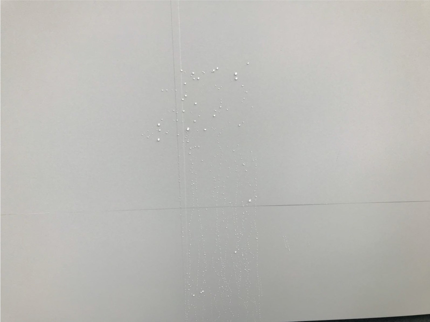
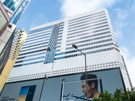
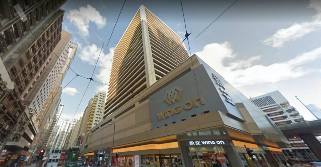
Photo : Wing On building in Sheung Wan was reported to have cladded with non-combustible cladding. Source from ejinsight on the pulse ( http://www.ejinsight.com)

In my next blog , I shall explain in details the “self-cleaning” being applied in aluminium cladding.


Boundaryless collaboration to turn state-of-art Architecture design into “down-to-earth” reality solution

In a highly congested urban context, how can a building stand out from the backdrop and become memorable ? There are strategies such as a practical internal layout, modern interior design and impressive building facade. Since buildings are usually arrayed in highly dense urban areas, the building facade becomes the first impression and first touch in many metropolitan cities. To create a distinct impression in international city likes Hong Kong, the architectural design created by powerful multi-cultural collaboration is the bespoke element underpinning the design solution.  

It is to the benefit of future users, landlords and every stake-holder of the development when the building is positioned and presented in the right site, right angle, right context and right location. To gear the architectural design toward practicality rich solutions, a down-to-earth technical analysis becomes profoundly important. K.P.D.O + GBE like many leading edge internationally award-accredited architects, believes a good balance of design, usage, layout, cost, and site features are essential to the development.

Grateful and thankful to collaborate, rather than presenting a simple yield diagram, K.P.D.O.+GBE. presented an aspirational solution showing the full site potential. K.P.D.O+GBE has analysed the details, negated technical deal breakers and prepared a sensible and approvable layout for the future user’s consideration. The turn-around for these are 6 days only. This assignment showcases and highlights our strong ability to find additional value whilst producing distinctive and memorable architecture.


“Loose of Neutral” in Electrical Circuit in traditional expensive residential apartment

The night scene of Hong Kong is always representing the prosperity and the stunning pictorial attraction for many people . The backdrop of the night scenery is the densely packed high-rise buildings being lit up.

With the air-conditioning became introduced in Hong Kong , some traditional luxury residential development was designed with 3 phases supply to cope with the loading consumption

Effect of Neutral Loss and Over-heat

The 3-phased live wiring is pairing with the neutral wire. The power runs into your apartment through “live” and return through “neutral . There is a defect called “nentral loose” which means the neutral wire loose contact or in bad connection. If there is “neutral loose” , that may be caused by various reasons, there will be abnormal arcing around the point of connection, a flash phenomena or spake fire will be occurred from time to time to heat up the already loose connection point and adversely causing unpredictable loading of electric current passing through the entire circuit. This circuit connects the load side appliance such as air-conditioners, the electronic parts or protection fuses of these electrical appliances may be damaged.

Inspection by Infra-red scanning and WR 2 checking

Unfortunately, it was not always detectable the abnormal heat up around the connection point . I prefer to adopt the infrared thermography scanning technique in my project or my inspection. However, the electrician today prefer to do by visual inspection which in my view may be subjective in some occasion. Our in-house infra-red is E4 model from FLIR. This is not the latest model, but still fit to our general routine checking.


Acoustic performance in Curtain Wall

Curtain wall system is such a complex external envelope of the building . It is more than an enclosure but also to serve to reduce heat gain and sound proof. The evaluation of  heat gain is commonly considered by the amount thermal transfer in the energy unit. Nevertheless , lesser attention is given to the acoustic consideration . Thank to my friend Dr Man and our peers Lixil who shares me one table. The airborne acoustic reduction is considered by STC value which varies as per the glass panes composition and thickness of glass. STC is to measure the degree of decibel reduction. The reduction is further related to the hertz of sound transmission. For easy communication , each composition of glass panes will be assigned the STC value. The interesting observation is that the “laminated glass” is achieving similar STC value compared to similar glass panes thickness of “insulating glass unit”. Furthermore , A 12mm thick single panes can achieve similar STC value to 6+12+6 insulating glass unit. Indeed, there are more consideration to the curtain wall acoustic including the impact-borne sound transmission caused by impact to the mullion or transom . Sometimes, the provision of the noise barrier or the provision of the balcony projecting out from the external facade can help to reflect the unwanted sound such as traffic away.


Protect your roofing membrane

When I was a boy, I saw the construction worker at roof heating up the Asphalt block with very bad odour smell. Bituminous asphalt were usually applied in liquid form in row by row with some over-lapping at even interval spacing. Although this materials are proven to be very weather resistance and durable once after curing and set, it is not encouraged to use in new works as per the General Specification (ASD) Clause 12.50. With the advancement of technology , there are now coming with various type of ready-applied roofing felt and some type are even in spraying form.

Nevertheless, the typical defects like blistering of membrane, sagging of membrane, incorrect surface water fall , poor outlet details , lack of backing rod for sealant in expansion, add-on structure impairing the roofing are still prevailing. These are attributed to the poor workmanship, lack of inspection and inadequate design details consideration. Indeed, even though the defects exists , it does not mean we have to end the life of roofing by complete re-roofing. A more sensible way is to carry regular inspection and maintenance than to leave the roof undue long time unattended.